【Unity】深度图(Depth Texture)的简单介绍 agile Posted on Oct 2 2021 优秀博文 > 本文由 [简悦 SimpRead](http://ksria.com/simpread/) 转码, 原文地址 [zhuanlan.zhihu.com](https://zhuanlan.zhihu.com/p/389971233) 前言 -- 在用 Unity 整 Hi-Z 剔除的时候由于需要处理深度图,作为小萌新,整着整着发现单单深度图相关的知识就可以水一篇文章,那就愉快的水起来吧。 首先我们先随便摆一个测试场景,如下图: 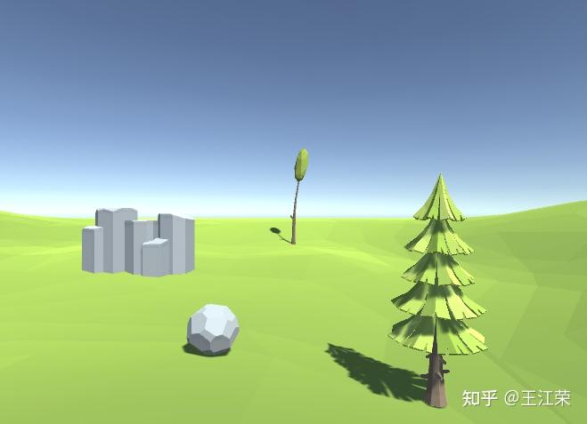 查看深度图 ----- 学过图形学我们知道,在渲染管线的光栅化阶段,GPU 会计算不透明物体的 Mesh 在对应像素上的深度(取值范围为 0-1 的浮点数),用它来判断像素上应该显示哪个三角形对应的数据。可参考: [王江荣:光栅化与深度缓存](https://zhuanlan.zhihu.com/p/363245957) 那么我们能不能查看这个深度图呢?Unity 提供的 **Frame Debugger** 可以帮助我们根据 draw call 查看每帧的渲染过程,我们点击 **UpdateDepthTexture** 项就可以查看到当前帧的深度图了,如下: 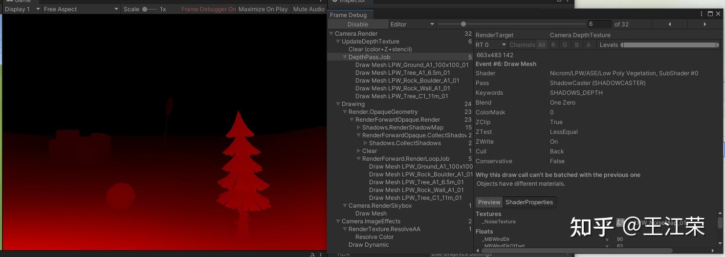 展开 UpdateDepthTexture,我们还可以看到每个 mesh 的渲染顺序: 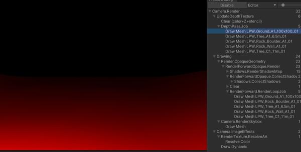 并且在 **RenderForwardOpaque.CollectShadows** 中我们可以看到深度图的应用: 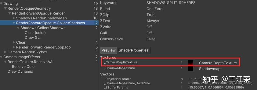 由于深度值只是一个浮点数,因此我们深度图的每个像素就不需要存储 rgba 四个浮点数了,**只需要 r 通道即可,因此我们看见的深度图是红黑色的**,这样可以减少的深度图所占用的内存空间。 从上面的深度图中我们可以看出当物体离 camera 越近,深度图上对应的区域越红(深度值接近 1),越远则越黑(深度值接近 0)。也就是说**深度值从 0 到 1 代表的是从远到近**。 很多人点 UpdateDepthTexture 的时候,可能会发现看见的深度图全是黑的(如下图)。这是为什么呢,难道场景中所有物体的深度都是 0,都靠近 far clip plane? 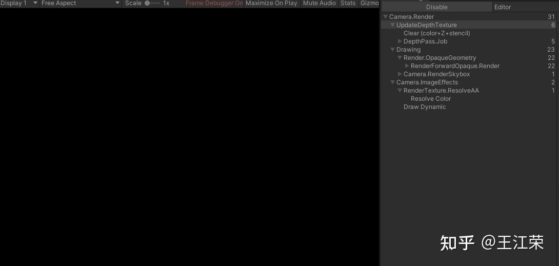 此外上面的深度图是在我们 platform 选择 Window(DirectX 11) 或 iOS(Metal) 时看见的结果(近红远黑)。若选择 Android(OpenGL ES3) 看到的深度图会是下面这么一番景象(近黑远红): 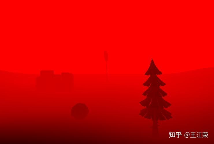 从 Android 平台下的深度图来看,深度值从 0 到 1 代表的是从近到远。 这些种种的问题或不同是为什么?我们从深度的计算入手。 深度计算 ---- 我们知道物体要显示在屏幕上要进过 MVP 变换到裁剪空间(Clip Space),在裁剪空间做完裁剪后,再做一次透视除法变成标准化设备坐标(NDC),我们来看看这个过程坐标发生了什么变换。 注:由于 OpenGL 和 DirectX 的投影矩阵和 NDC 范围有所不同,所以分开来说。有关 OpenGL 和 DirectX 的投影变换矩阵可参考: [王江荣:视图变换和投影变换矩阵的原理及推导,以及 OpenGL,DirectX 以及 Unity 的对应矩阵](https://zhuanlan.zhihu.com/p/362713511) 由于我们一开始在 Window 平台,所以先来看看 DirextX 的深度计算方式。 假设某个顶点在 MV 变换后坐标为  (其中  的值也被称之为:eye Z value),那么 P 变换后得到的齐次坐标为: >  上面得到的齐次坐标即是顶点在**齐次裁剪空间**下的坐标。 注:DirectX 的视图空间是左手坐标系,式子中的 f 代表 far clip plane 的 z 的值,n 代表 near clip plane 的 z 的值,  。 我们将  和  分别代入 z 的值中  因此**在裁剪空间中,z 值的取值范围为 (0,f)**。 裁剪空间的坐标要转成 **NDC** 坐标还需要做一次**透视除法**,即齐次坐标 (x,y,z,w) 内所有值都除以 w。那么上面的齐次坐标做完透视除法后的值即为: >  由于要计算的是深度,我们不用管 x,y 的值,只需要关注 NDC 中 z 的值即可: >  将它们分别代入到上面的式子中可得到: >  因此 DirectX 下  的取值范围为 0 到 1,其中 0 代表物体在 near clip plane 上,1 代表在 far clip plane 上。而 DirectX 下的深度值即是  的值,  。 但是不对啊?按照前面深度图的显示,明明是 1 代表物体在 near clip plane 上,0 代表在 far clip plane 上,怎么和计算出来的结果正好**相反,**这是因为 Unity 为我们做了一次**反转的操作**,即: >  官方文档说明如下: > 在 DirectX 11, DirectX 12, PS4, Xbox One, Metal 这些平台上反转了深度的方向,使得在 near clip plane 上深度值为 1.0,逐渐减小到 far clip plane 上深度值为 0.0。并且在裁剪空间下 z 的范围也由 (0,far) 变为了 (near,0) 。 [Writing shaders for different graphics APIs](https://docs.unity.cn/2021.1/Documentation/Manual/SL-PlatformDifferences.html#5) 此外我们在 Unity5.5 的版本更新中,也能看见相关的介绍,链接如下: [undefined](https://docs.unity3d.com/Manual/UpgradeGuide55.html) 为什么要进行反转操作呢?我们来看一个例子,假设 n=0.1,f=10,那么不反转的话,  和  的关系如下: 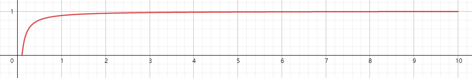 从曲线图中看出深度随着距离的增长是一个**非线性**的增长(有点像 log 函数),当  时,  的取值范围大概在 (0, 0.95) 之间,而当  时,  的取值范围大概在 (0.95, 1) 之间。也就是说**当物体越接近 near clip plane 那么深度值的精度就越高,而越接近 far clip plane 精度就越低**。例如当两个物体距离分别是 9 和 9.1 的时候,如果精度不够,就很难通过深度来判断两个物体到底谁在前面,就可能会发生闪烁的现象(一下认为你在前面,一下子认为它在前面),这种由精度产生的问题我们称之为 **z-fight**。 然后我们来看看反转后的曲线,如下: 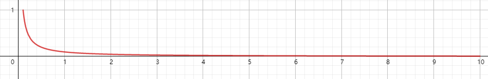 好像没什么软用,不还是接近 near clip plane 时精度越高么,只不过值从接近 0 变成了接近 1。事情并不是这么简单,这里我们要引入**浮点数精度分布**的知识,即**浮点数本身在越接近于 0 的时候精度越高**,也就是说越接近 0 浮点数的分布越密集。这样你就会发现反转后,虽然当  时,  的取值范围大概在 (0.05, 0) 之间,但是这个区间内分布的浮点数却非常的多,从而保证深度值的精度不会受到特别的大的影响。 参考: [小试刘刀:精度优化 --ReversedZ 提高 zbuffer 精度](https://zhuanlan.zhihu.com/p/33905480) 因此反转操作有利于在 near 特别小而 far 特别大时,整体保证不错的精度效果,从而减少 z-fight 现象。 其他避免 z-fight 的方法: * 物体不要放的太近,防止使用深度无法区分两者的远近关系。 * near clip plane 设置的尽可能远。但这样可能造成离 camera 很近的物体被裁剪掉,需要多测试找到一个适合的距离。 * 使用更高精度的 depth buffer,例如 Unity5.5 的更新里说到将 24 bit 的 depth buffer 更换为了 32 bit,当然这样会增加内存的开销。 * 尽量缩短 n 和 f 之间的距离,例如 n=1,f=8 的曲线示意图如下。 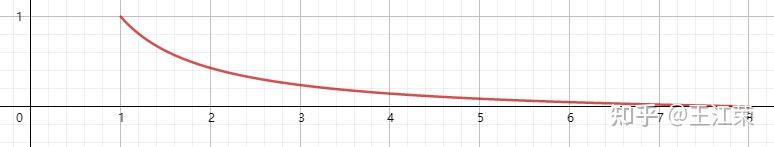 因此最终结论就是 **Unity 在 DirectX 平台上(Metal 与之一样),depth 的取值范围是 1 到 0,当在 near clip plane 上时 depth=1,在 far clip plane 上时 depth=0**,其计算公式为: >  我们可以简单的验证下是否正确,例如之前的测试场景,我们设置 Camera 的 Clipping Planes 的 Near 为 6,Far 为 100,对应公式中的 n 和 f: 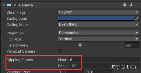 然后创建一个 Cube 使其离摄像机的距离为 10.5,因为 Cube 的宽度为 0.5,因此此时 Cube 离 Camera 最近的一个面的距离正好为 10,对应场景和深度图如下: 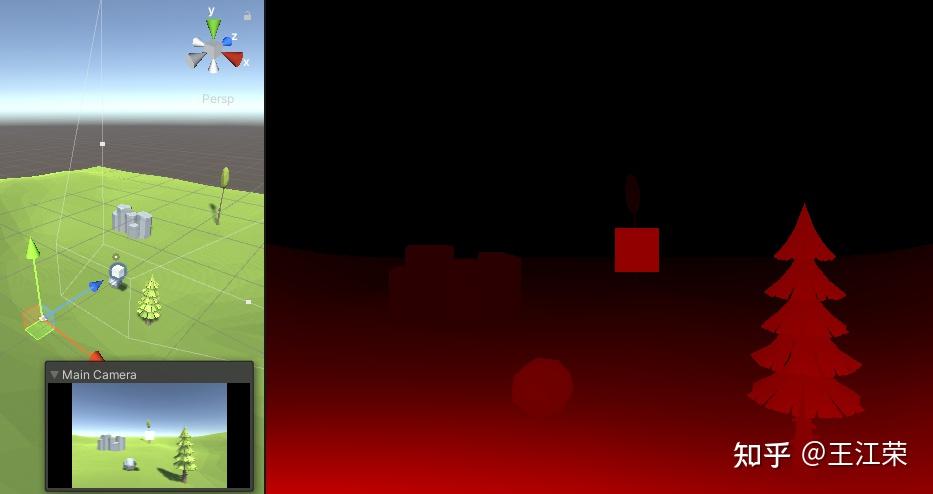 将这些值代入公式得到 depth 为:  换算成 r 通道的值即为:0.574*255=146,我们采样一下深度图中小方块的颜色,可以发现正好是对应的,如下图: 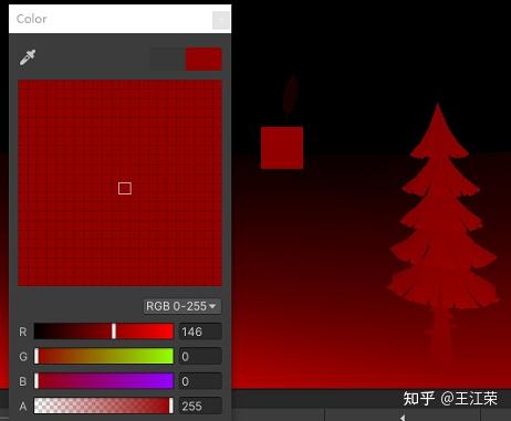 同时这个公式也可以解释为什么有些时候深度图是全黑色的,因为默认的 Camera 的 n=0.3,f=1000,如果代入公式会发现小方块的 depth 变为了 0.03,接近黑色。对应示意图如下: 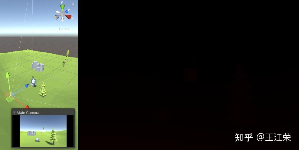 接下来我们再来看看 OpenGL 的,同样假设在 MV 变换后坐标为  ,那么 P 变换后得到的齐次坐标为: >  这里需要注意的是 OpenGL 的视图空间是右手坐标系,而式子中的 f 和 n 分别代表 far clip plane 和 near clip plane 离原点的距离,  且  我们将  和  分别代入 z 的公式中得:  因此**在裁剪空间中,z 值的取值范围为 (-n,f)**。 然后转换为 NDC 坐标即为: >  >  继续将  和  分别代入公式中得: >  因此  ,由于深度值的范围为 (0,1),所以我们还需要做一个转换,即:  ,并且由于 Unity 并没有对 OpenGL 的深度值进行反转(可见之前发的官方文档连接),因此 **Unity 在 OpenGL 下最终的深度值计算公式为**: >  depth 的取值范围是 0 到 1,当在 near clip plane 上时 depth=0,在 far clip plane 上时 depth=1。 同样我们可以用之前的方法切到 Android 平台下验证一下,将 n=6,f=100,  (因为 OpenGL 是右手,Unity 是左手,所以在 Unity 中 Cube 相对 Camera 的 z 为 + 10 但是代入 OpenGL 的公式时要取反)代入公式当中得到:  对应的 r 通道值即为 0.426*255=108,参考图如下: 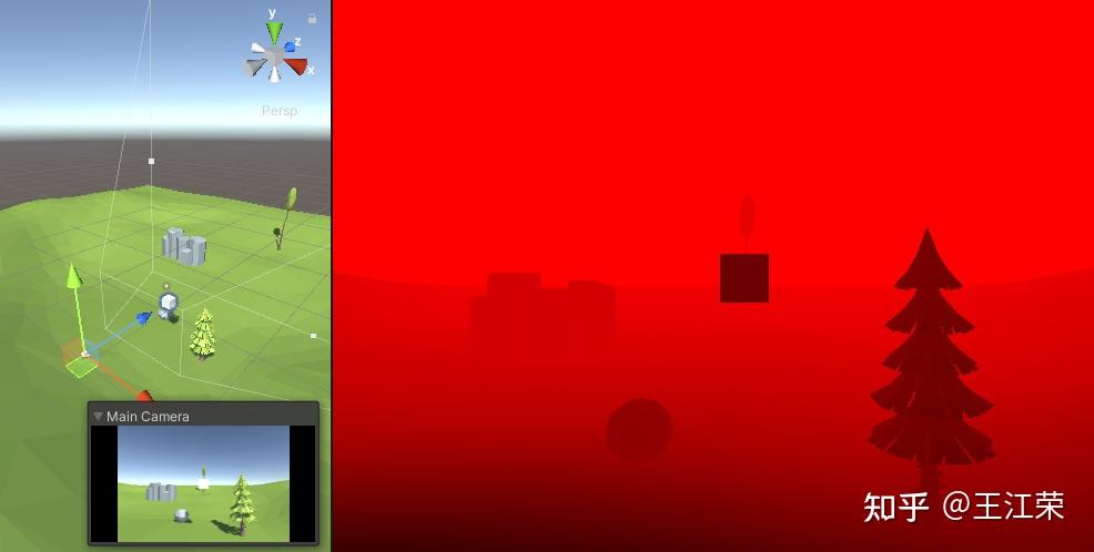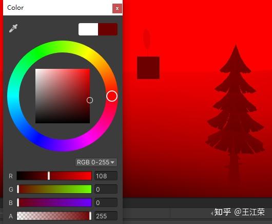 总结一下: 在类似 Direct3D 的平台上,例如 Direct3D, Metal 和 consoles,它们的裁剪空间 z 值范围为 (0, f),深度值范围为 (0,1)。Unity 平台对 DirectX 11, DirectX 12, PS4, Xbox One, Metal 进行的深度反转,使得这些平台下裁剪空间 z 值范围为 (n, 0),深度值范围为 (1,0)。 在类似 OpenGL 的平台上,例如 OpenGL, OpenGL ES2 和 OpenGL ES3,它们的裁剪空间 z 值范围为 (-n, f),深度值范围为 (0,1)。 上面所有的范围,第一个数指的都是 near clip plane 所在的值,第二个数为 far clip plane 所在的值。 获取 / 采样深度图 ---------- 前面简单的介绍了下深度图的计算方式,而当我们要使用深度图制作一些特殊效果的时候,例如深度剔除,景深效果等,就需要我们对深度图进行采样,然后根据获取到的深度做处理。 那么我们怎么才能获取到深度图并且采样呢?官方给出的答案如下: [Cameras and depth textures](https://docs.unity.cn/2021.1/Documentation/Manual/SL-CameraDepthTexture.html) 简单来说在 Unity 中,Camera 可以生成 depth,depth+normals,motion vector 三种 texture。这些 texture 在可以帮助我们实现一些很牛的效果,而其中的 depth texture 就是我们要的深度图。 我们可以通过设置 Camera 的 **depthTextureMode** 属性来使 Camera 生成对应的 texture,例如下面代码可以使 Camera 生成 depth texture(开启后会造成一定的性能消耗): ``` Camera.main.depthTextureMode |= DepthTextureMode.Depth; ``` 运行后,可以从 Camera 组件中看到如下提示:info:renders Depth texture  如果我们的 Rendering Path 使用的是 Deferred 或是 Legacy Deferred(如下图),那么生成深度图并不会造成额外的消耗,因为使用 Deferred Shading 本身就会把深度信息写入到 G-buffer 中。 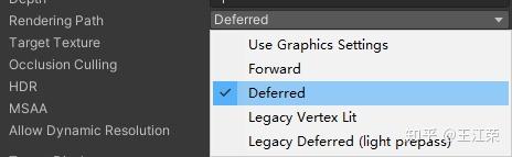 Depth texture 的大小和屏幕大小相同,其中每个像素的值的范围在 0 到 1 之间(计算方式前面介绍了),非线性分布(参考前面的曲线图,后面会细说),精度根据不同的平台可能是 16bit 或 32bit。支持深度图的平台有如下几种: > Direct3D 11+ (Windows), OpenGL 3+ (Mac/Linux), OpenGL ES 3.0+ (iOS), Metal (iOS) and consoles like PS4/Xbox One 注:OpenGL ES 2.0 (Android) 需要有 GL_OES_depth_texture 扩展,WebGL 需要有 WEBGL_depth_texture 扩展才能支持深度图。 我们的深度图在 Shader 的 **ShadowCaster** Pass 中被渲染,因此如果 shader 不支持 shadow casting(即 shader 中不包含 ShadowCaster 的 Pass 并且 fallbacks 的 shader 也没有),那么使用这些 shader 的物体不会被渲染在深度图上。 举个例子,我们新建一个 SurfaceShader,然后场景中的建个 Cube 使用该 Shader,可以看到该 Cube 被渲染到了深度图中,如下图: 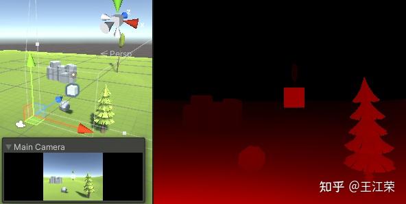 这是因为我们新建的 shader 中,默认 fallback 了 Diffuse shader,而 Diffuse 中就带有 ShadowCaster Pass,因此我们的 Cube 会被写入到深度图中。 ``` FallBack "Diffuse" ``` 如果我们删掉这句再看看,就会发现深度图中没有了这个 Cube,如下图: 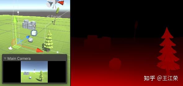 除了通过 fallback 别的带有 shadow casting pass 的 shader 的方法外,对于 SurfaceShader 我们还可以通过添加 **addshadow** 指令来使得系统自动生成对应的 shadow casting pass,如下: ``` #pragma surface surf Standard fullforwardshadows addshadow ``` 当然了,除了上面两种方法外,我们也可以自己写一个 ShadowCaster Pass 来使得物体能够被渲染进深度图。除此之外,只有不透明物体(render queue <= 2500)会被渲染进深度图。 那么当我们设置了 Camera 的 depthTextureMode 为 Depth,生成了 Depth texture,怎么使用(采样)呢?Unity 在 shader 中为我们提供了一个名为 **_CameraDepthTexture** 的全局变量,我们对其进行采样即可。 例如在 fragment shader 中采样深度图: ``` sampler2D _CameraDepthTexture; float4 frag(v2f input) : Color { float depth = tex2D(_CameraDepthTexture, input.uv); return float4(depth, 0.0f, 0.0f, 1.0f); } ``` 采样的代码,一般也会写成下面这种形式: ``` float depth = UNITY_SAMPLE_DEPTH(tex2D(_CameraDepthTexture, input.uv)); ``` 其中 **UNITY_SAMPLE_DEPTH** 的作用就是取 r 通道的值: ``` //HLSLSupport.cginc #define UNITY_SAMPLE_DEPTH(value) (value).r ``` 当然了,我们也可以在 C# 端利用 **Shader.GetGlobalTexture** 来获取深度图,然后用 **Graphics.Blit** 方法将其复制到 RenderTexture 上(这也是做 Hiz 剔除时重要的一环)。 这里需要注意的是,在 Unity 的生命周期中有很多的事件函数,例如 Start,Update,OnRenderObject 等等,官方文档介绍如下: [undefined](https://docs.unity.cn/2021.1/Documentation/Manual/ExecutionOrder.html) 那么我们应该在哪个事件中获取_CameraDepthTexture 才能保证是当前帧的深度图呢?经过测试,**建议在 OnPostRender 中获得到当前帧的深度图**,如下: ``` void OnPostRender() { Graphics.Blit(Shader.GetGlobalTexture("_CameraDepthTexture"), renderTexture); } ``` 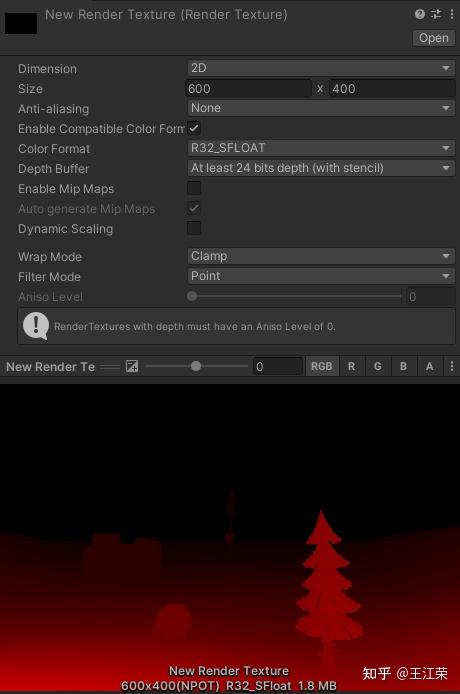 注:有时在 OnPreRender 或者 Update 函数中获取_CameraDepthTexture,那么得到的深度图将会是 Scene 窗口下的深度图,具体原因暂时不明~ 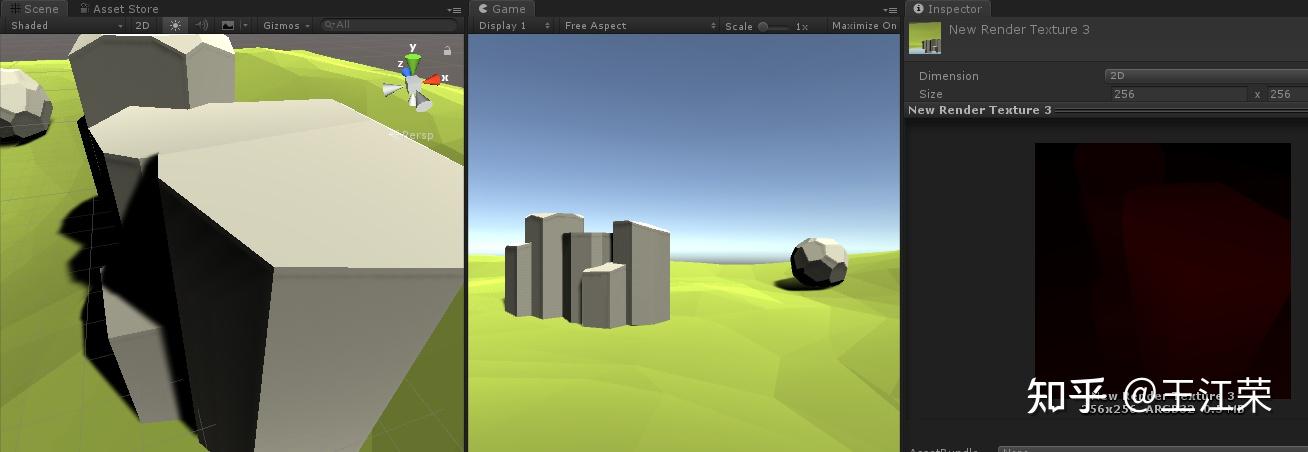 有关 **_LastCameraDepthTexture** 的用法自己还没整明白,后续再研究研究,按文档的意思可以用来生成低分辨率的 DepthTexture。 当然了,我们做东西肯定要考虑跨平台,前面提到了不同平台生成的深度图是不同的,如 DirctX 近到远是 1 到 0,OpenGL 近到远是 0 到 1,那么怎么统一采样的值呢?根据前面的介绍我们知道 DirctX 等平台之所以是 1 到 0 是因为 unity 为其做了反转,那么我们再把它们转回来不就得了么。而对于这些进行了深度反转的平台,unity 都定义了名为 **UNITY_REVERSED_Z** 的宏,因此如果想要各个平台近到远都是 0 到 1,就可以这么处理: ``` sampler2D _CameraDepthTexture; float4 frag(v2f input) : Color { float depth = tex2D(_CameraDepthTexture, input.uv); #if defined(UNITY_REVERSED_Z) depth = 1.0f - depth; //d3d, metal to do it #endif return float4(depth, 0.0f, 0.0f, 1.0f); } ``` 非线性转线性 ------ Depth texture 中每个像素代表的深度值是一个非线性的变化,例如前面 n=0.1,f=10 的深度变化曲线如下图:  这样有一个坏处,比方说我们想用深度图做一个扫描线的效果,如下图: 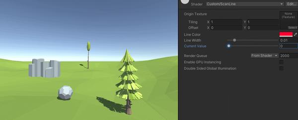 我们的扫描线应该随着深度的变化而变化,那么就会有个问题,例如曲线图所示,当我们深度从 1 变化到 0.05 的时候,实际上代表的距离仅仅离相机不到 1,我们的扫描线只能匍匐前进,甚至都看不到。而深度从 0.05 变化到 0 的时候,啪的一下就瞬移的。而我们期望的肯定是**随着深度的变化,扫描线的移动(也就是距离)也匀速的变化,这就是所谓的线性关系**。 为了解决这个问题,Unity 为我们提供了一个 **Linear01Depth** 的方法,可以得到一个线性变化的深度值。 ``` //UnityCG.cginc // Z buffer to linear 0..1 depth inline float Linear01Depth( float z ) { return 1.0 / (_ZBufferParams.x * z + _ZBufferParams.y); } ``` 里面的_ZBufferParams 的参数定义如下: ``` //UnityShaderVariables.cginc // Values used to linearize the Z buffer (http://www.humus.name/temp/Linearize%20depth.txt) // x = 1-far/near // y = far/near // z = x/far // w = y/far // or in case of a reversed depth buffer (UNITY_REVERSED_Z is 1) // x = -1+far/near // y = 1 // z = x/far // w = 1/far float4 _ZBufferParams; ``` z 值的计算公式我们前面已经提到过了,我们代入到 Linear01Depth 方法中来看看为什么它返回的结果是线性的。 对于 DirectX 这类深度反转的,_ZBufferParams.x = -1+far/near,_ZBufferParams.y = 1,得到公式: >  对于 OpenGL,_ZBufferParams.x = 1-far/near,_ZBufferParams.y = far/near,得到公式:  好家伙,**就是视图空间下的 z 值除以 far clip plane 的值**,对应的函数图即为: 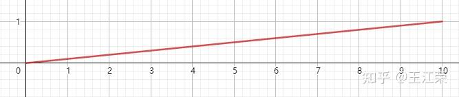 从中可以看出,使用 Linear01Depth 需要注意的有两点: * 不管深度是否反转,得到的结果都是从近到远是从 0 到 1。 * 深度和 near clip plane 的值无关,等于 0 时,代表在相机原点,而不是在 near clip plane。 除了 Linear01Depth 方法外还有个 **LinearEyeDepth** 方法,**其实就是通过深度反推出视图空间下 z 的值**(  ),方法体如下: ``` //UnityCG.cginc // Z buffer to linear depth inline float LinearEyeDepth( float z ) { return 1.0 / (_ZBufferParams.z * z + _ZBufferParams.w); } ``` 简单的套一下 Direct 的公式:  使用深度图 ----- 深度图的一些使用场景,先贴几个参考,后续抽空自己实现下再完善: [Unity Shader - 深度图基础及应用](https://www.jianshu.com/p/80a932d1f11e)[undefined](https://blog.csdn.net/puppet_master/article/details/77489948)[神奇的深度图:复杂的效果,不复杂的原理 - 慕容小匹夫 - 博客园](https://www.cnblogs.com/murongxiaopifu/p/7050233.html) 【Unity】使用Compute Shader实现Hi-z遮挡剔除(Occlusion Culling) 纹理映射(Texture mapping)